81 ford granada marquis (engine cooling & air conditioning)
One of the most important considerations when fitting a bigger engine in a car is engine cooling and with the engine now over double the size, the original engine radiator just wasn’t going to give enough cooling, so a bespoke radiator was needed and with the air conditioning to also consider as much air flow as possible was also needed.
Engine cooling
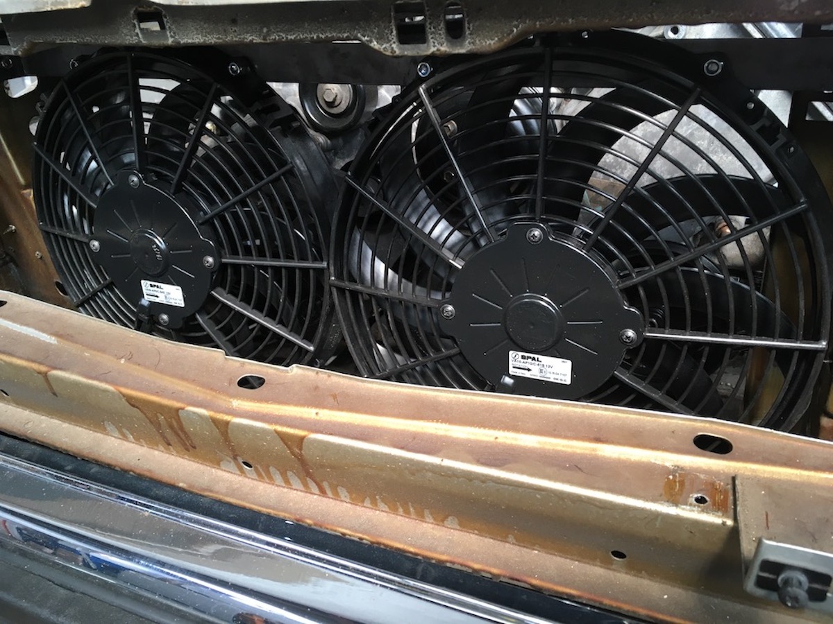
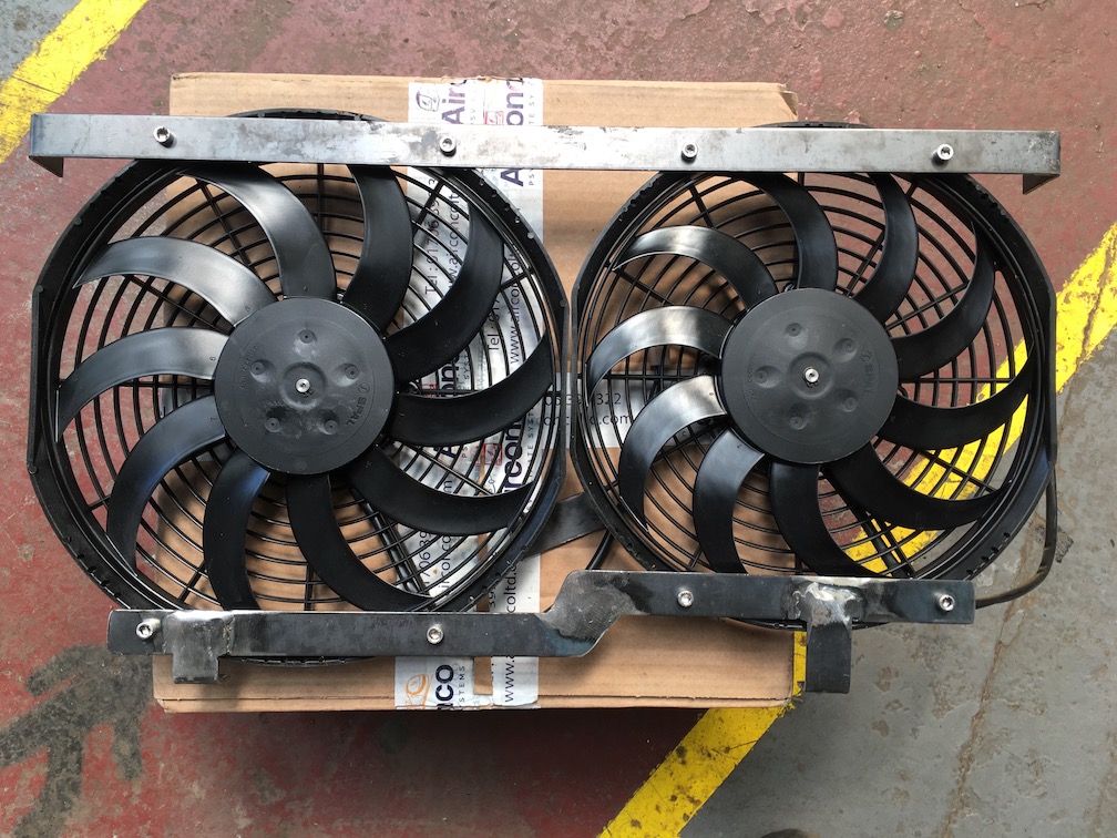
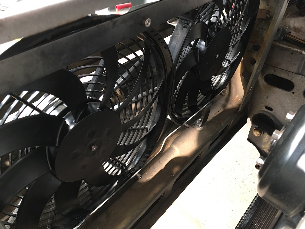
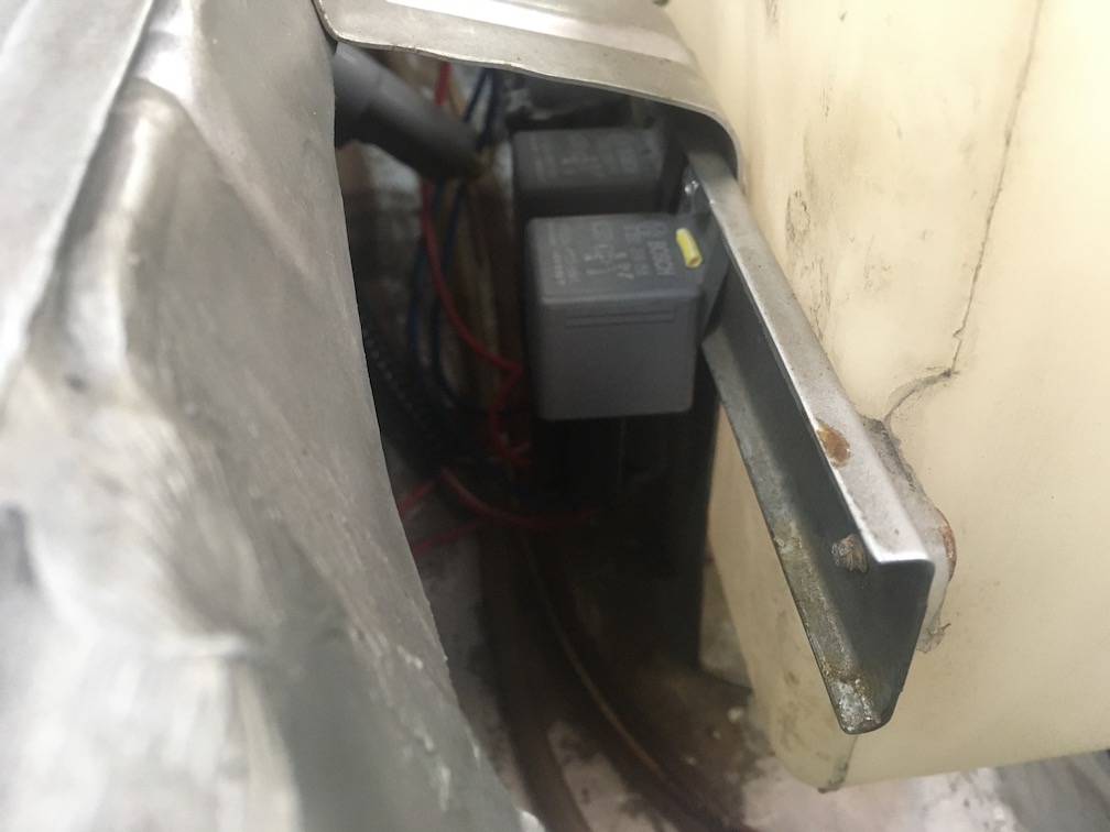
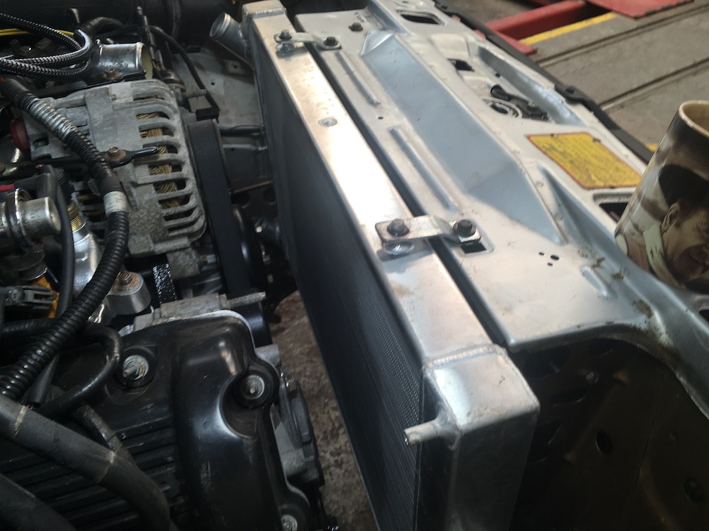
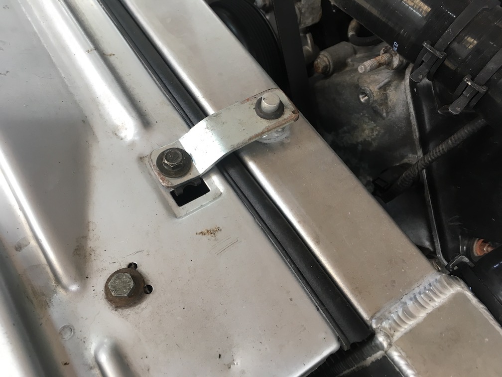
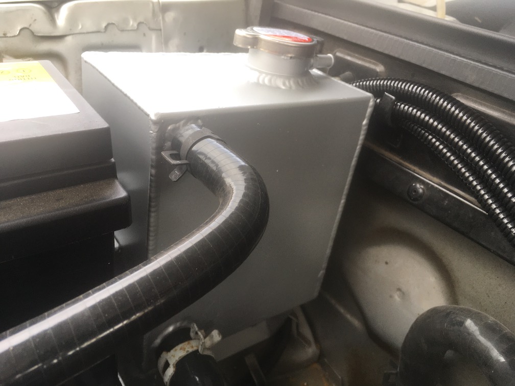
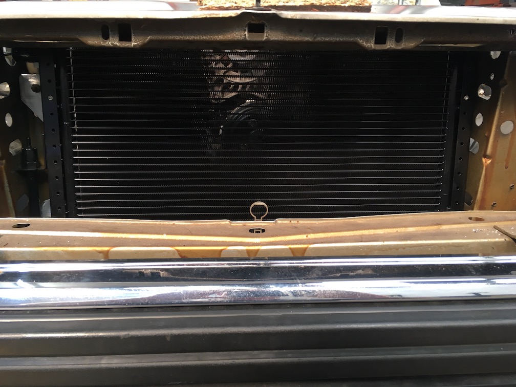
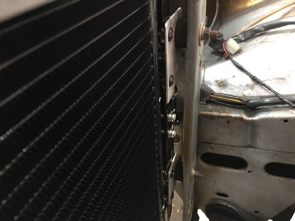
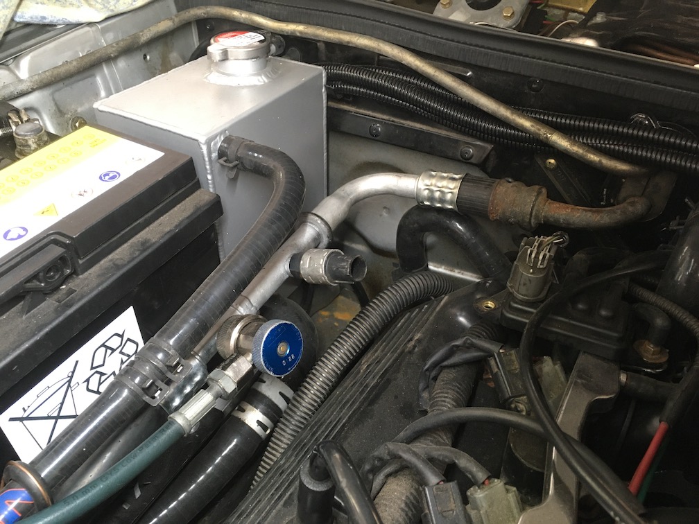
After taking a few measurements I determined the best option for the most forced air flow would be one 11 inch (28cm) fan and one 12 inch (30.5cm) fan, I made some brackets and mounted the two fans in the space infront of the radiator. The radiator was made by Custom Made Rads to my specifications of the maximum size that would fit in the space available, it turned out that the total coolant capacity was actually 1.7 UK pints (0.95 litres) bigger than the original Mercury cooling system. When it came to wiring the cooling fans I mounted two relays behind the waser reservior, one relay is switched by the low speed output from the PCM and the other relay switched by the high speed fan output from the PCM. Finally I mounted a 3.5 UK pint (2 litre) coolant expansion tank and used silicone hoses to connect everything. After some initial test runs I discovered when the fans were on a lot of air was escaping between the radiator and slam panel so filled the gap with some self adhesive draft excluder
Air Conditioning
Right from the inception of this project it was my intention to retrofit an air conditioning system, the donor car came with a working A/C compressor, it was a relatively easy task to fit a universal condenser, receiver/drier and make some pipework but the real sticking point was finding an evaporator, TXV and evaporater case. After nearly 9 months of looking and 6 months into the build a “breaking for spares” Granada listing popped up on Ebay, after striking a deal with the guy I loaded up some tools and set of on the nine hour round trip to procure an evaporator assembly and associated pipework. Now I was all set to install some air conditioining.
The Condenser and Receiver/Drier
The condenser is the air conditioning radiator that usually fits infront of the engine cooling radiator and is used to condense the refrigerant gas leaving the evaporater back into a liquid and to disperse the heat extracted from the passenger cabin, as it was always my intention to fit air conditioning I had fitted a condenser earlier in the build.
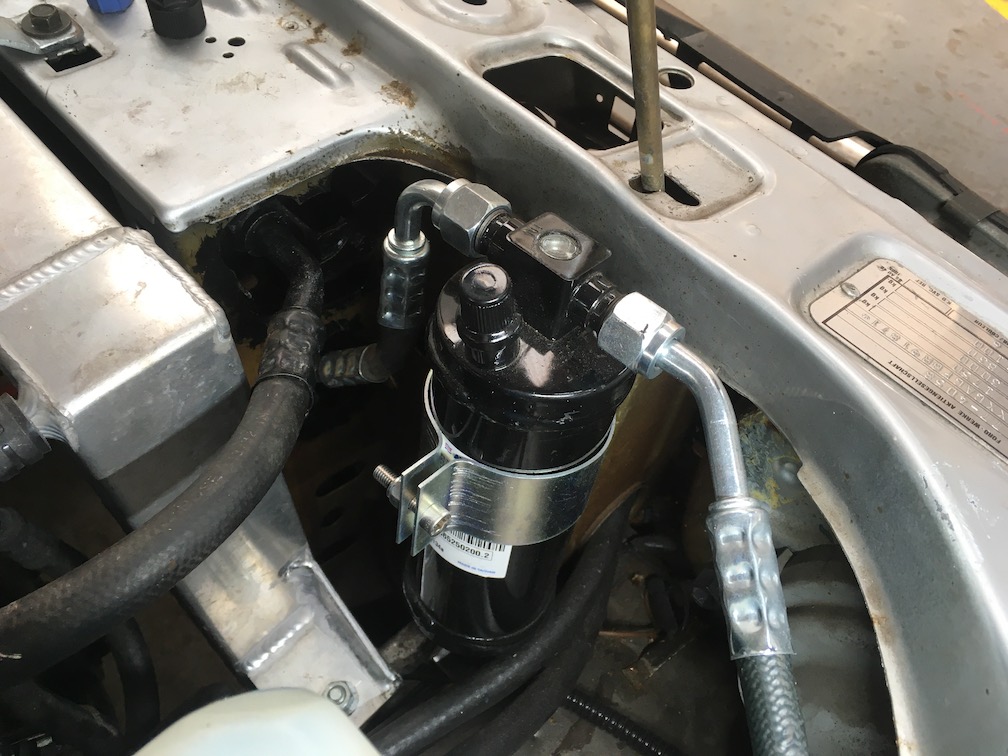
The receiver/drier fits in the air conditioning pipework between the condenser and evaporator and is used collect, filter and dry the liquid refrigerant leaving the condenser.
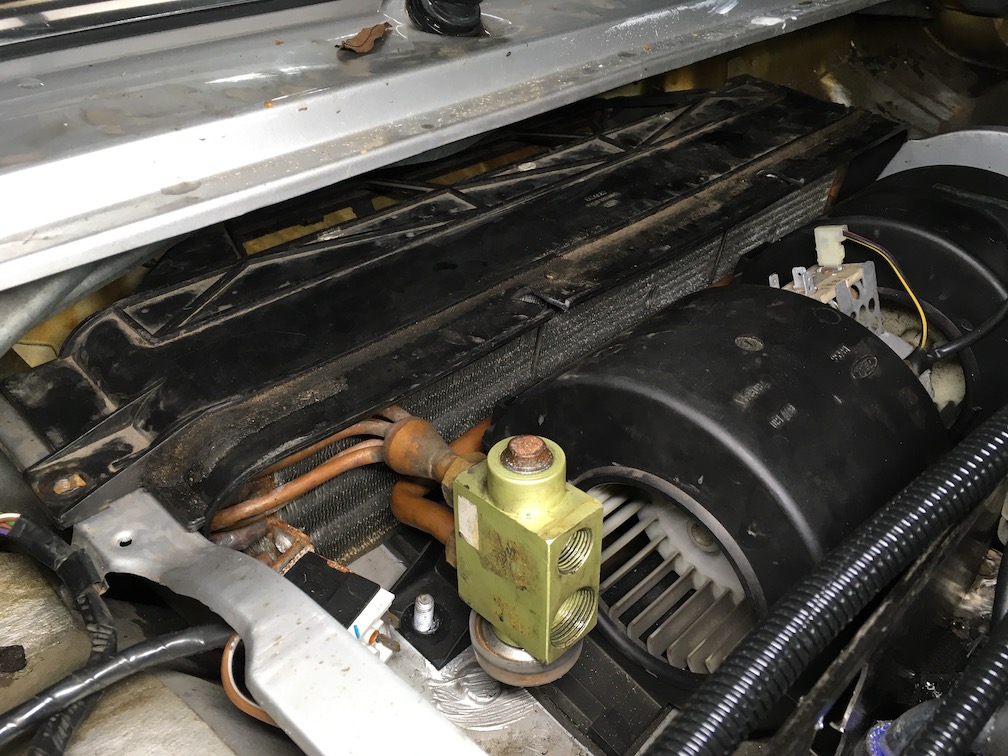
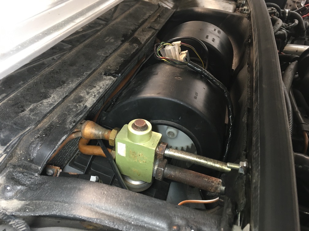
The Evaporator
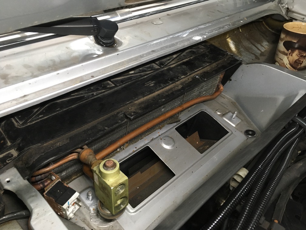
Liquid refrigerant from the condenser under high pressure of usually around 150 – 200psi (10.3 – 13.8 Bar) is forced into the evaporator through a variable orifice called a TXV (Thermal Expansion Valve), the TXV regulates the flow of refrigerant to prevent icing of the evaporator by maintaining a low pressure in the evaporator of usually around 23 psi (1.5 Bar). The high pressure refrigerant entering the low pressure of the evaporator causes the refrigerant to boil extracting the heat in the pasenger cabin by a blower fan moving air over the evaporator.
I had to make a couple modifications to the evaporator case before fitting by removing the recirculation door and valve as my Granada didn’t have cabin air recirculation feature, I also had to fit the evaporator upside down in the case so that the pipework would be on the opposit side, this resulted in the TXV also being mounted upside down.
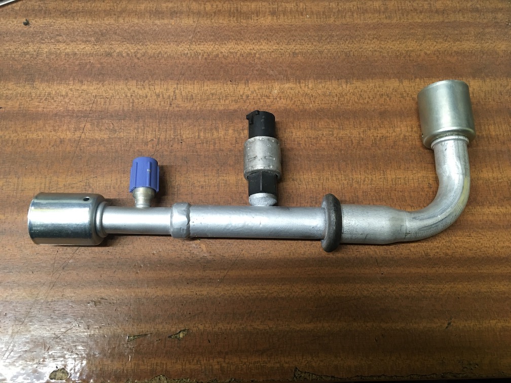
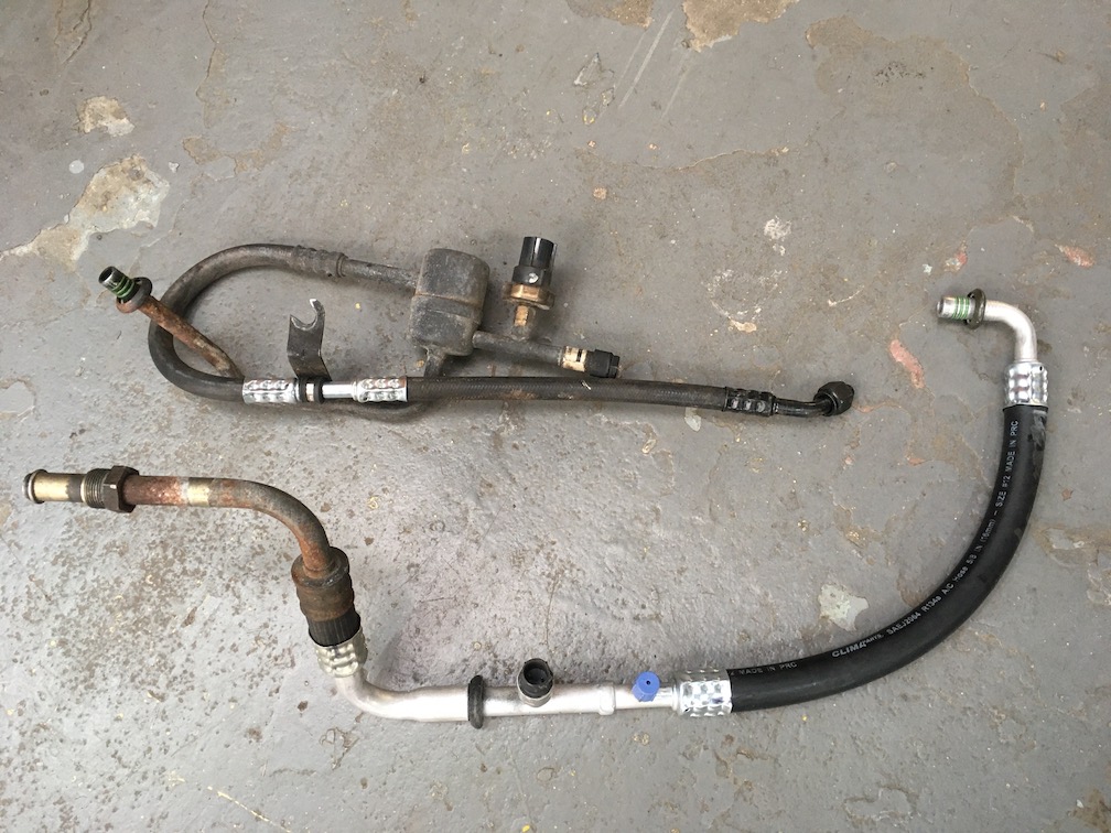
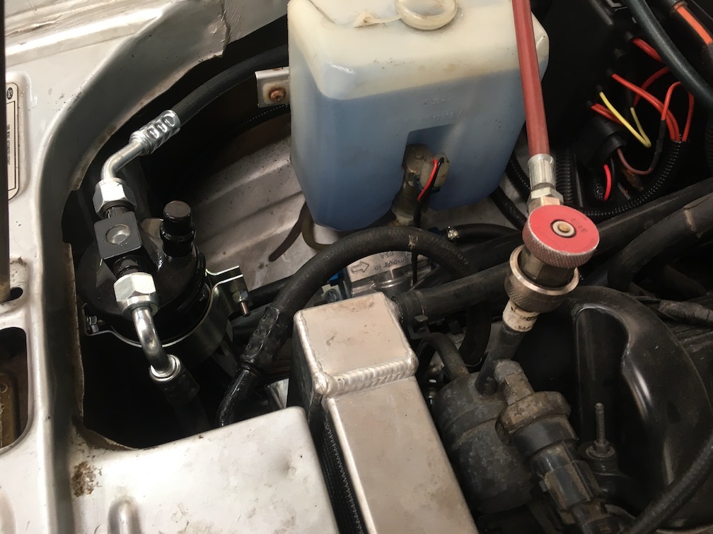
The Pipework
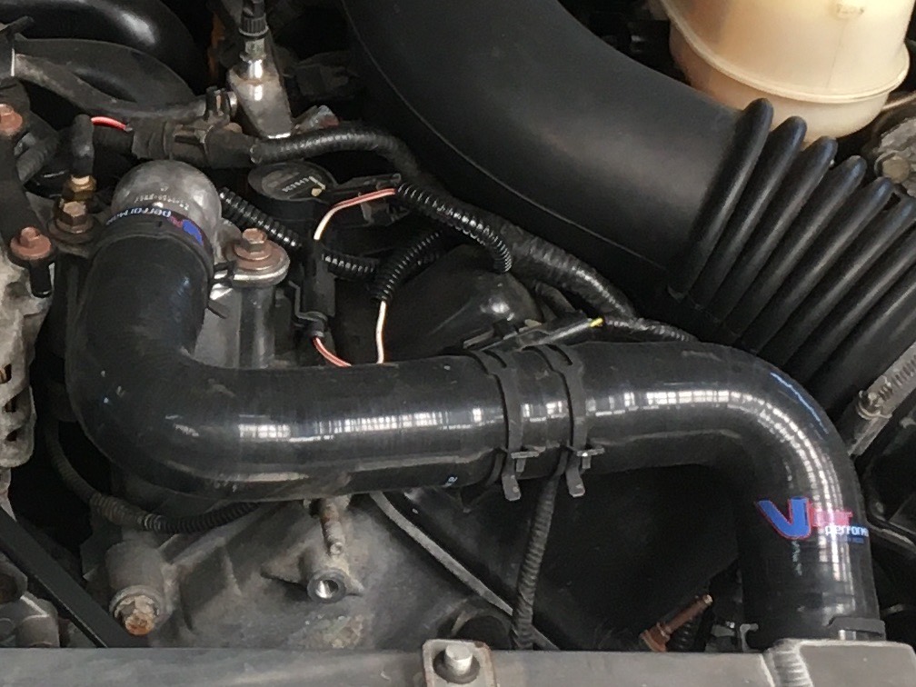
Now that all the components were inplace it was time to make some pipework to connect them.
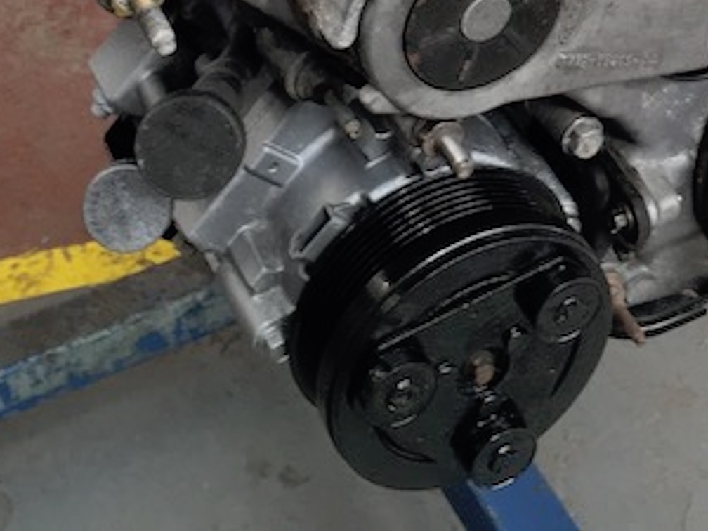
The Compressor & Switch
The driving force of an air conditioning system is the compressor, its job is to suck the refrigerant gas from the evaporator and compress it through the condenser and receiver turning it back into a liquid to once again be turned back into a gas in the evaporator.
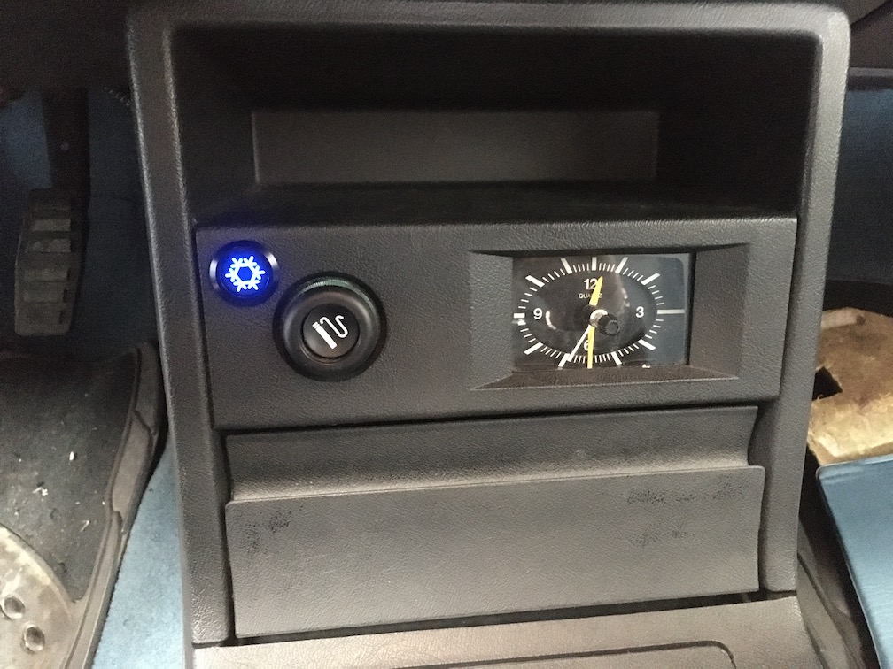
Finally I had to power the air conditioning and fit a switch to turn it on/off, see the wiring diagram link below to see a wiring diagram
more information about the ford granada marquis
Please follow the links below to find out how the 1981 Ford Granada Marquis was created. (Click on pictures to see at full size)
- The concept (Find out why Granada Marquis here)
- Build preparation
- Fitting the engine
- Transmission & driveline
- Brakes, steering & suspension
- Exhaust
- Speed control
- Engine cooling & air conditioning
- Speedometer, tachometer & immobiliser
- Wiring & wiring diagrams
- Miscellaneous
- Specifications
- Gallery of finished vehicle
- Back to Derecks MOT Centre homepage
- Back to the Ford Granada Marquis home page
